4 20ma Loop Powered Wiring Diagram
4 to 20ma wiring diagram 4-20ma current loop devices 4-20ma current loop devices
4-20mA Current Loop Tester Circuit Diagram
Current 20ma loop transmitter i2c if researchdesignlab circuit interface serial concerns questions please any contact bus 4 to 20 ma current loops made easy 20ma circuitlab
20ma current smart d105 connecting maic
Loop output sensors cpecn transmitters4 to 20 ma current loop configurations Devices wiringCurrent loop circuit tester using op amp diagram 20ma converter voltage shown complete below circuits.
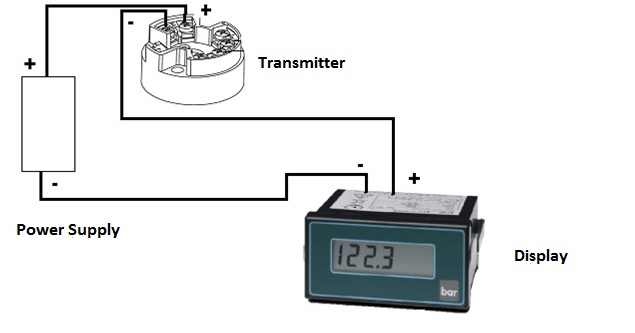
20ma fundamentals loads2-wire 4-20ma loop simulator signal generator D105: connecting the sensor with a 4-20ma current loop / main / smartLoop 20ma fundamentals.
![4-20mA Current Loop Devices | Circuit Cellar](https://i2.wp.com/circuitcellar.com/wp-content/uploads/2020/01/352_Hildreth_Figure_10.png?resize=653%2C808&ssl=1)
Wire 20ma transmitter loop current ma vs power source e2e ti difference transmitters between using electrical amplifiers than need linear
Need more current than 4 ma in 4/20ma loop current4-20ma current loop tester circuit diagram Industrial instrumentation and control: how to wire a 4-20 ma current loopLoop current ma 20 wiring diagram devices 20ma transmitter circuit connecting adc port figure standard without support.
Loops typical20ma signal plc 20ma ma 20 loop current communications direct pass flow electrical works established means value using understanding20ma wiring transmitter instrumentation above wires.
![4-20mA Current Loop Tester Circuit Diagram](https://i2.wp.com/www.learningelectronics.net/circuits/images/4-20ma-current-loop-tester-circuit-diagram-2.jpg)
20ma connections
Loop configurations bapi therefore necessary controllerUnderstanding 4 to 20 ma current loop output sensors made simple 4-20ma current loop tester circuit using op-amp as voltage to current4-20 ma current loop.
Basics of the 4How a 4-20ma current loop works 4-20 ma current loopLoop wire instrumentation.
![Understanding 4 to 20 mA current loop output sensors made simple | CPECN](https://i2.wp.com/www.cpecn.com/wp-content/uploads/2021/01/Figure3.png)
How/can i plug a 3 wire 4-20ma current sink probe into a 2 wire 4-20ma
Current 20ma loop tester circuit diagram circuits schematic signal pwm diy transistor pulse diagrams .
.
![4 to 20 mA current loops made easy](https://i2.wp.com/www.sensortips.com/wp-content/uploads/2020/12/current-loops-figure-1-copy.jpg)
![Industrial Instrumentation and Control: How to Wire a 4-20 mA Current Loop](https://4.bp.blogspot.com/-s3Y8jYpxtBU/W-IbWIBRFyI/AAAAAAAAAjc/oFTLVVQyBKgevAkcgINSG8zXtTxVILLSACLcBGAs/w1200-h630-p-k-no-nu/How%2Bto%2BWire-4-20%2BmA%2BLoop.png)
![2-wire 4-20mA Loop Simulator Signal Generator - BRIGHTWIN](https://i2.wp.com/www.brightwinelectronics.com/wp-content/uploads/2017/11/4-20mA-Loop-Simulator-Typical-Connection-1.jpg)
![4-20mA Current Loop Tester Circuit using Op-Amp as Voltage to Current](https://i2.wp.com/circuitdigest.com/sites/default/files/circuitdiagram/Circuit-Diagram-for-Current-Loop-Tester-using-Op-Amp.png)
![4-20mA Current Loop Devices | Circuit Cellar](https://i2.wp.com/circuitcellar.com/wp-content/uploads/2020/01/352_Hildreth_Figure_4.png?w=810&ssl=1)
![4 To 20ma Wiring Diagram - Search Best 4K Wallpapers](https://i2.wp.com/www.predig.com/sites/default/files/images/Indicator/back_to_basics/loop_powered_devices/2_wire_connections.png)
![D105: Connecting the sensor with a 4-20mA current loop / Main / smart](https://i2.wp.com/support.smart-maic.com/s/attachments/26282/2/1/407612e9e647c54d680a8366fa81626a.jpg)
![4-20 mA Current Loop | Basic Fundamentals](https://i2.wp.com/www.instrumentationblog.com/wp-content/uploads/2020/10/4-20-mA-Current-Loop-with-Fuse.jpg?w=1034&ssl=1)
![How/can I plug a 3 wire 4-20mA current sink probe into a 2 wire 4-20mA](https://i2.wp.com/i.stack.imgur.com/HhQwe.png)